VRFs
Categories:
4 minute read
Overview
VRFs can be used to route and/or nat and filter what traffic is allowed to pass and how it should appear on the network. VRFs can be associated with an interface whether it be a physical interface / virtual network interface or other tunnel interfaces such as IPSEC or GRE. VRFs are segmented on a layer 3 level from all other traffic traversing the Trustgrid node.
For standard use cases of source nat and/or destination nat creating a route and a NAT is sufficient. Traffic rules can be used for more advanced controls. An applicable ACL is required for any traffic to pass as a zero trust methodology is applied.
Address Translation
This is where NATs are created in order to translate the traffic to appear as desired on the network. NATs support translating both source and destination CIDRs as well as masquerading as the egress interface address.
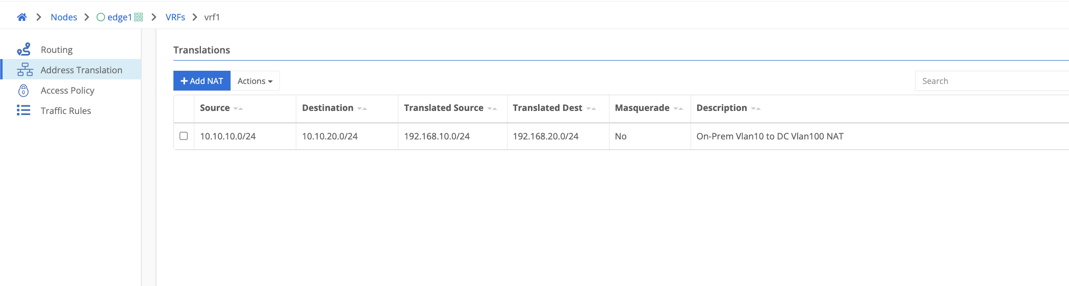
SNAT / DNAT Example
Using the example NAT below if a source packet was initiated from 10.10.10.100 destined for 10.10.20.100 the source address would be translated to 192.168.10.100 and the destination address would be translated to 192.168.20.100. It is important to note that nat translations occur before routing decisions are made.
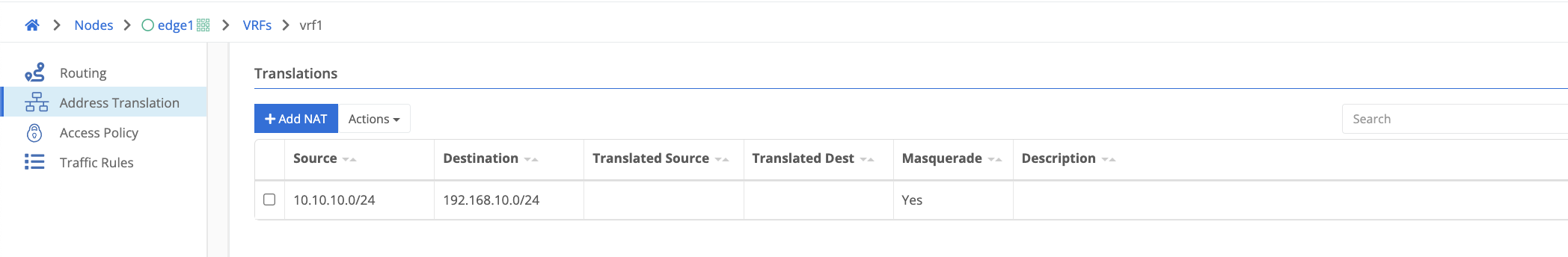
Masquerade Example
Using the example below, if a source packet is initiated from within 10.10.10.0/24 destined for anything in 192.168.10.0/24, the source would be translated to the interface address from which the packet is egressing. If it were a single interface Trustgrid node it would be sourced as the wan facing interface address.
Routes
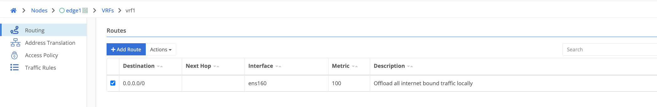
Note that NAT translations happen before routing so routes should be created for the destination NAT CIDR if applicable. Routes require a destination CIDR, interface, and metric. A next hop is optional and only applicable for non-tunnel interfaces such as physical interfaces or VLAN subinterfaces. The gateway of the applicable interface will be used if no next hop is defined.
The example below would be used for example to offload all internet-bound traffic directly out of the WAN facing interface
Traffic Rules
Traffic rules can be used for more advanced granular traffic manipulation beyond standard source and destination nat. There are many more parameters that can be applied to the traffic depending on the specific use case. When creating a traffic rule an ACL is required for traffic to pass. The available parameters are defined below. Rules are evaluated based on the line number. The first matching rule is the one that will be applied to the packet. More specific rules should always be implemented above less specific rules. Eg a rule for a /24 network should be above a /16 network the /24 is included in.
| Field Name | Description |
|---|---|
| Number | The line number the rule is applied to. Rules are matched in numerical order. |
| Action | All traffic rules have an action that is applied to the associated packet.
|
| Ingress Interface | The traffic rule is applied to packets that ingress on this interface |
| Forward Interface | Packets are forwarded out this interface once the rule is applied |
| Protcol | The protocol that the rule should apply to. All, ICMP, TCP or UDP |
| Forward VRF | Packets are forwarded into another VRF that is associated on the node. Only configureable when a forward action is selected. |
| Source CIDR | The source network the rule should apply to |
| Destination CIDR | The destination network the rule should apply to |
| Masquerade | Translate and source all packets from the nodes interface address when enabled |
| DNAT Destination | Forward all traffic to the DNAT destination IP/Port. For example in order to forward all http traffic through a proxy |
| Destination MAC | The destination MAC address defined overwrites the source MAC address of the packet. Necessary only for some container deployments such as Snort inspecting traffic. |
| Ports | Used to define a port range when creating a traffic rule |
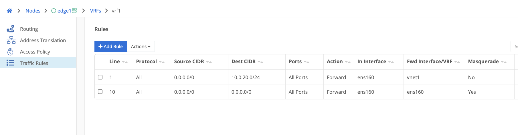
Traffic Rule Example
In the below example, the first rule on line number 1 is forwarding all traffic destined to 10.0.20.0/24 to a virtual network tunnel interface. Any NATs configured under Address Translation will be applied before the packet is forwarded to its destination. The rule on line number 10 will forward all traffic that does not match the first rule out to the internet masquerading as the WAN interfaces address. If the line numbers were reversed the virtual network rule would never be matched as all traffic would match the internet offload rule which is configured for all source and destination traffic.
Feedback
Was this page helpful?
Glad to hear it! Please tell us how we can improve.
Sorry to hear that. Please tell us how we can improve.